Van Racking Side Panels – Information Base
Technical reference for codes, sizes, and CNC toolpath operations for Standard and Wheel-Arch side panels.
Overview
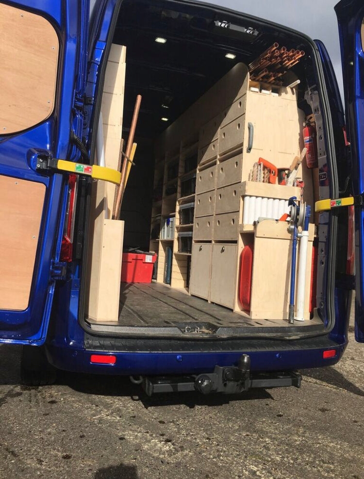
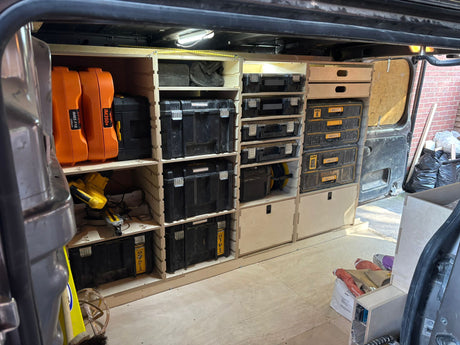
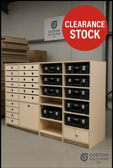
Side panels form the primary structure of each unit. CNC profiled for alignment with shelves, tops, and wheel-arch components. Heights from 700–2400 mm (custom height on Unlimited only) (standard: 1000, 1200, 1500, 1775). Depths 322mm slim depth, 380mm standard depth or up to 440 mm (unlimited)
Mortices are 12 mm by design. Some sheet batches may need minor manual adjustment depending on sheet batch thickness.
Side Panel Coding
| Segment | Description | Example |
|---|---|---|
| STD / WA | Standard side / Wheel-arch side | STD-1500-ST-SD-380 |
| [Height] | 700–2400 mm (std: 1000, 1200, 1500, 1775) | 1500 |
| [Top] | ST Standard Top · FT Flat Top | ST |
| [Depth] | SD-380 Standard · SL-322 Slim (where applicable) · Custom up to 440 mm | SD-380 |
| [SP] (optional) | Groove spacing modifier (e.g. SP-120). If absent, default spacing. | SP-120 |
Standard Unit Sides (STD-[Height]-[Top]-[Depth]-[SP])
Depths up to 440 mm.
Toolpath Operations
- Fixing holes — Ø3 mm drill, through.
- Back-stay mortices Dog Bones — 12 mm through, Ø10 mm cutter.
- Top mortices — only if ST; 12 mm through, Ø10 mm..
- Fixed shelf bracket recess — Ø10 mm profile inside, 1 mm deep + Ø3 mm drill.
- Grooves — 6 mm deep, -0.3 offset, Ø10 mm cutter.
- Perimeter profile — Ø10 mm if sides-only sheet; Ø6 mm if mixed sheet.
Wheel-Arch Unit Sides (WA-[Height]-[Top]-[Depth]-[SP])
Depths up to 440 mm.
Toolpath Operations
- Fixing holes — Ø3 mm drill, through.
- Back-stay mortices — 12 mm through, Ø10 mm cutter.
- Top mortices — only if ST; 12 mm through, Ø10 mm.
- Bottom mortices — always present; 12 mm through, Ø10 mm
- Fixed shelf bracket recess — Ø10 mm profile inside, 1 mm deep + Ø3 mm drill.
- Grooves — 6 mm deep, -0.3 offset, Ø10 mm cutter.
- Wheel-arch alignment holes — 2 × Ø6 mm drill, through (align with WAS-L/R).
- Perimeter profile — Ø10 mm if sides-only sheet; Ø6 mm if mixed sheet.
Solid Back Units will include the following.
- Solid Backs — 6 mm deep, -offset depending on sheet thickness, Ø10 mm cutter. Including selection of 3mm fixing holes at 200mm centers
Downloads
Download: Sides – Toolpath Operations (PDF)
Need different spacing? Use SP-XXX codes. If omitted, default spacing applies.
latest Update 16/10/25 12.41am